
Table of Contents:
During the 1980’s, I worked in the machine shop of a factory that made showers, valves and industrial metering equipment. I had several jobs there over a period of 14 years, including Machine Setter, Production Engineer and Quality Control Inspector. I mostly worked in a machine shop, where metal components were made.
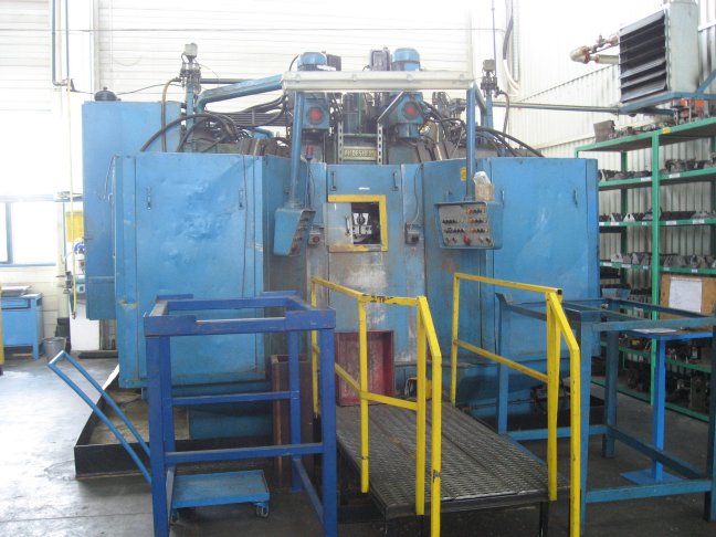
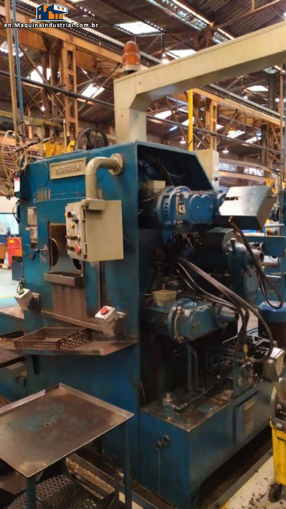
This is quite a long post about a machine called a Diedesheim AMII (or AM2, AM-2, AM 2, AM-II, AM II etc.). I’ve written about this machine before, in the post Career Change: From Producing to Computing, but only briefly touched the surface of what this machine really was. In the factory where I worked, we had two of them. One was an older model (from the late 1960’s I think) and the other a newer one from the 1970’s. The operating principles were the same on both machines and whilst they performed the same functions, the newer one was my favourite, mainly because it had bigger guards around it and you had enough room to get in and set it without having to contort into uncomfortable positions. The older one had slightly smaller guards, restricting the working space, hence the uncomfortable positions.
What does it do? It is a high volume machining platform, that could utilise up to twelve sets of tools to perform cutting, drilling or threading operations on either a cast workpiece or solid material. As we used it to machine castings (mainly brass or DZR shower bodies) that’s what I’ll be referencing in this post. It could also machine solid blocks of material, but we never used it for that – we stuck to castings!
How the hell does that work, I hear (probably) nobody ask.
I’ve tried to put as many pictures as I could find in this post, in an attempt to explain this wondrous machine. Where there are larger images, the text [Click the image below for a larger version] will be somewhere close to the image.
The Diedesheim AMII: A Wondrous Story
The AMII is this: a 12 spindle, 5 station, 3 axis rotary transfer machine with horizontal indexing turret.
It required a person (the operator) to stand at the front of the machine, usually on a platform. The machine was quite big (explained later) and the bit where you had to place the casting or material to be machined (and retrieve the finished article) was about half way up the vertical height of the machine.
The operator would remove a finished, machined object from the front of the machine through a sliding door. They would then place a fresh unmachined casting in the front, clamp it by operating a foot pedal and (having checked that it was clamped correctly) slide the door shut. The door would operate a switch which started the machining process by rotating the turret and sending all the tools in to start their cutting/threading process.
And that was it. It was high volume (most I ever got was 340 pieces per hour), it was quite noisy and it used oil as coolant. The operators hated it, as the cooling oil was smelly and despite the all around guards, it usually went everywhere, including all over the operator. The operator had to wear wellington boots, aprons (yes plural) and gloves as a minimum. It was also – as it ran quite quickly – quite hot. Cutting brass at high volumes created a lot of heat, taken away by the oil coolant. In summer, it was extremely unpleasant to operate.
It was also quite delicate, in the sense that it was set up to minimise machining time. Therefore, you set the tooling to fast travel to millimetres from the face of the start of machining, before slow travelling to cut. That meant that if a casting had a large piece of flashing on it, or the operator hadn’t lined the casting properly in the chuck jaws, the tooling could crash into the casting and break.
If that happened, you would have to stop production and fix it – which could take a few hours, if you had to reset a tooling cluster.
Sometimes, operators misaligned castings in the jaws just to make it crash, knowing that they would have to go and do another job. But the other job wasn’t the AMII.
Why am I writing this?
I’ve mentioned in previous posts, I used to set these machines up for production. There are bigger machines in the world, but these were the biggest in the factory. It took a fair amount of skill to set them up, especially if you were against the clock.
I thought these machines were magnificent. There were no electronics in them whatsoever, they were purely electrical and hydraulically operated machines. Everything was set with toggle switches and limit switches, gearboxes and a dial indicator on a magnetic stand. If you wanted to move a toolset by 0.1mm, you did that with a dial indicator, a 17mm spanner and a 19mm socket with 5″ extension on a ratchet. You didn’t do it by typing on a keyboard, that’s for sure!
The machine was only half the story. When you had a casting to machine (e.g. a shower body), you had to use a toolset: a cluster of tools that rotated at speed, bolted to a spigot. You would have tools that roughed out surfaces and then fine turned them in the next station along. The fine turning tools set just behind the rough turning tools. You also had balanced tools – you couldn’t have one tool on one side of the spigot, you had to have two – one either side. If you didn’t, it would be slightly out of balance and would cause chatter (vibration on the surface of the metal being cut, resulting in a rough surface). And of course your two tools had to cut exactly the same, in tandem at the same time.
It was having the ability to not only set the machine itself, but to install, maintain and troubleshoot the toolsets that separated the people that could set the machine and those that couldn’t. There weren’t many that could set and maintain it perfectly – and I don’t like to blow my own trumpet, as it were – but I was one of the ones that could.
When I wrote the Career Change post, I mentioned that these electro/hydraulic machines quickly became obsolete, as CNC machining became fashionable. On the CNC machines, it didn’t take 30 minutes to move a tool 0.1mm, it took seconds as you could type it in. Then as the CNC machines became better and better, it marked the end of the old machines and they have now fallen into the annals of history.
When I did the research for the Career Change post, I looked up as much as I could about the AMII machines. I could find very little about them, other than Diedesheim was bought out by another German company that made big machine tools. Rotary transfer machines are still being manufactured today, by many companies, including the child company of the original Diedesheim company, but of course they’re all CNC now.
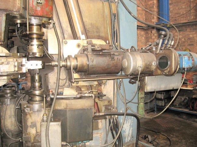
I managed to find a few pictures of an old AMII, I’ve put them in where applicable (NB: it’s not the machine I worked on).
Given that there’s so little information around about these machines, I thought I’d write something down about them, if nothing else so that I don’t forget them! So I’ve documented below the various aspects of running and setting these machines.
If you’re interested in traditional machine tools (or you’re James May), it might be of interest to you.
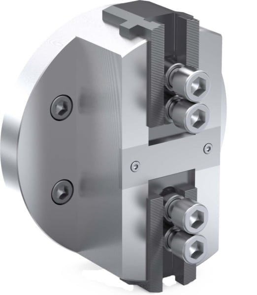
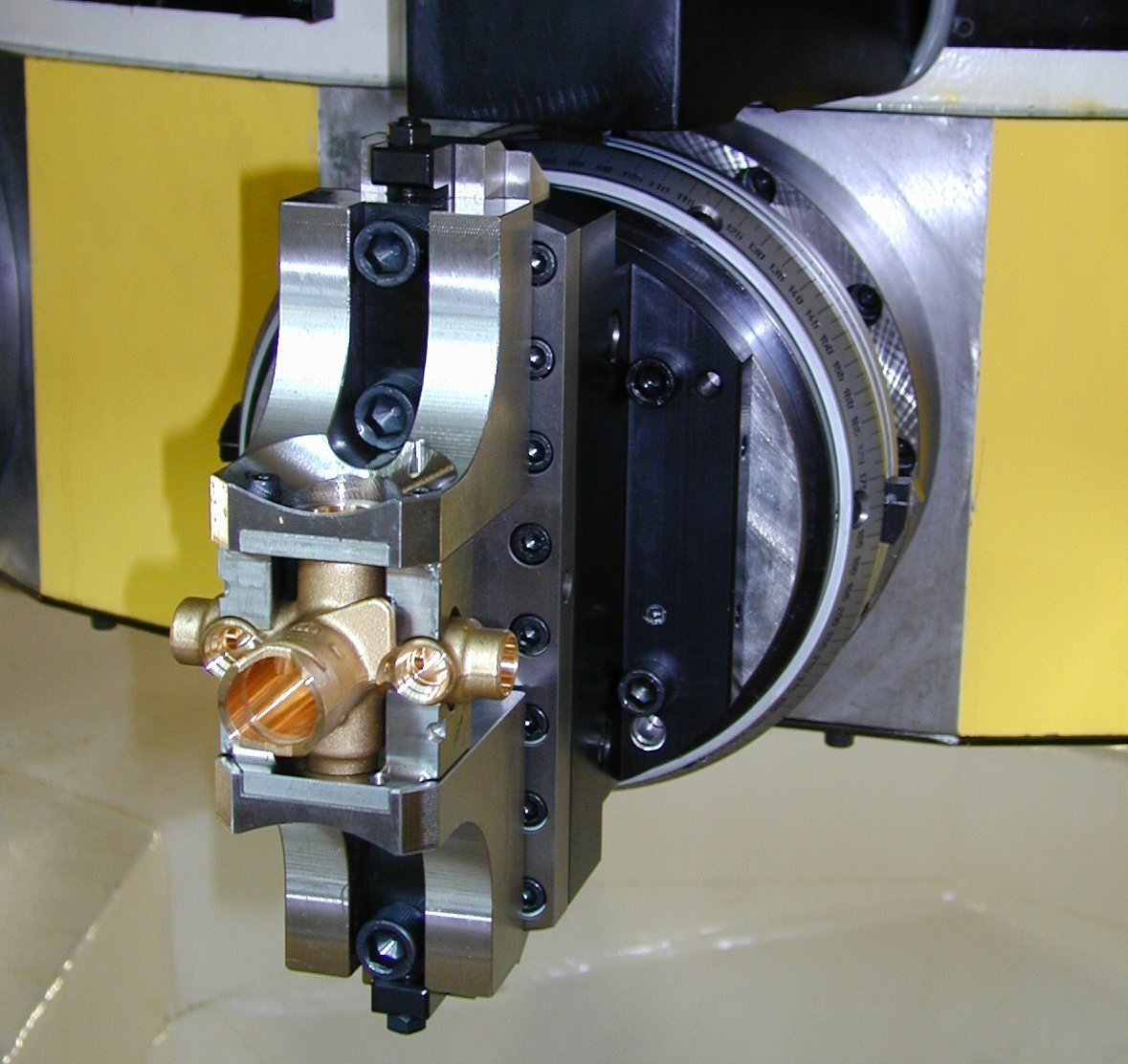
The Turret
We’ll start with the main (and biggest) part of the machine: the turret. The AMII has four machining stations and one load/unload station. The turret is a five-sided hollow slab, around 4 feet wide (about 1 1/4 metres) and roughly 12-18 inches tall. In the centre of each face was a hydraulic piston. A chuck was bolted to the face and attached to the piston, so that the in and out movement of the piston translated to a side motion on the two chuck jaws.
[Click the image on the left for a larger version]
The chucks stayed on the machine all the time (except for maintenance) and you bolted various sets of jaws to the chucks, depending on the casting you were going to machine. The jaws were operated by a foot pedal in front of the machine, actuate once to clamp, then once again to unclamp.
The safety devices on the machine were mainly microswitches. The operator station had an up-and-down sliding door with a bit of clear Perspex in it, so the operator could see if the turret had rotated. In reality, you couldn’t see through the Perspex, as the hot oil had made it cloudy over time, so the operator relied on the noise of the machine. Once it had rotated, all of the tools would engage at once – the noise was unmistakeable! If the operator raised the door as the turret was rotating, the turret would stop turning. Once the door was closed, it stayed there until the setter was called (me) and I had to reset it.
[Click the image on the right for a larger version]
The turret rotated 72 degrees every time (five faces). When it rotated around, it was very important that it stopped in the same place, every time. In other words, the dead centre of the turret face had to be exactly 72 degrees round at each turn, otherwise the machine tools would make their cuts in the wrong place. The turret achieved this by dropping down, rotating then pushing up to engage in a set of pins and castellations that would locate it in exactly the same place on each 72 degree rotation.
After a while of constant use (it took quite a while) we could detect small changes – discrepancies – in some of the measurements. This would be down to pin wear on the turret and they had to be replaced. It was quite a task to reset the turret: dial indicators, engineering blue, quite a lot of steel shims and very frustrated maintenance people.
There was a noticeable difference between the speed of rotation of the turrets between the two machines in the factory. The older one span much faster than the newer one (no idea why!) and so the operators could make better time on their piecework! We tried speeding the rotation up on the newer turret to match the older one’s speed (it’s all hydraulic, you just adjust a valve with an Allen key!), but we found that it wouldn’t engage the locating pins properly and so we left it slow (because we couldn’t be bothered to find out why, mainly).
The jaws
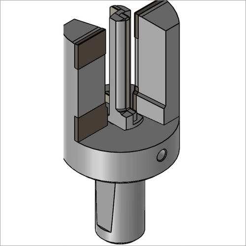
The jaws – the bits of metal bolted to the two jaw chuck – were just as important as the tooling. Most of the time we were trying to grip complex casting shapes that could vary slightly in shape and size. If that was the case, the jaws were made by cutting out the profile using something like spark erosion in the toolroom, to match the shape.
[Click the image on the left for a larger version]
It was also quite important to be able to hold the casting or workpiece in place, whilst the tooling did their work. The grip pressure was variable on the jaws, too loose and the casting would move (and possibly destroy your tooling in the process), too tight and you were at risk of distortion. The turrets were designed to cut holes and cut threads etc. if the jaws were set too tight, the holes they cut would be round until the jaws released and then they would “boing” into an ellipse. Sometimes, that didn’t matter, sometimes that was critical.
Another critical aspect was where the jaws were set in relation to the cutting stations. Most of the time there would be a horizontal drilling process that would require the hole to be dead centre of a casting. You had to make sure the jaws were positioned in the right place for that, otherwise you could end up with skew holes. And nobody wants that.
The jaws would have to be made so that it was easy for the operator to place the component in them, in the same position, every time. Operators were paid by the component, they needed to be as quick as possible (without breaking anything!).
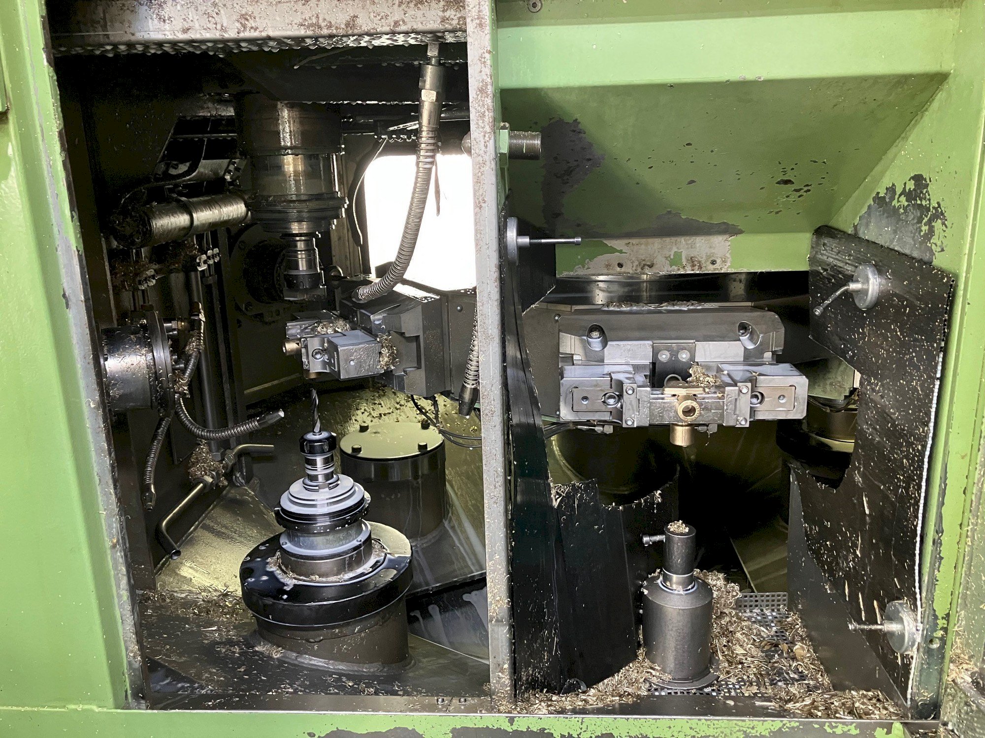
The machining stations (units)
Of the five turret positions, one station was loading/unloading and four stations did the cutting and machining etc. inside the machine i.e. behind big guards and not exposed to the operator.
Twelve motorised spindles (called units) were available in the machine, three for each of the four turret stations. Two units were positioned vertically, top and bottom acting up and down. One unit was positioned horizontally, acting in and out.
Each of the four turret stations were numbered: 20 to 50 with each of the units numbered 1,2 and 3. So for the first machining station (20), the bottom (vertical) unit was numbered unit 21, the horizontal unit was numbered 22 and the top (vertical) unit numbered 23. The next face around were numbered 31, 32, 33 and so on around until the last ones 51,52 and 53.
The horizontal units could be moved up or down. The whole unit sat on a big plate, which was located in slides that had long jacking screws running down them. If you wanted a hole at the top and the bottom of a component, you could achieve this by jacking up one horizontal unit and letting down another. Jacking of the units was done by hand: a 19mm socket and a ratchet. And elbow grease.
The spindles linear motion was hydraulic, with electric motors and gearboxes fitted on each one to provide the turning motion at the end of the spindle. You could vary the speed that the spindles rotated by selecting different gears, by manipulating handles on the side of the spindle gearbox (like a lathe). Each spindle had a round flange fitted at the end (that did the rotation), with four M10 bolt holes drilled and tapped into them and a hardened female location spigot. The spigot also had a hardened morse taper to fit a standard morse taper drill or tap holder on some units.
The units had different capabilities. Some were just a drilling/boring function, others were combination drilling and threading and a few were drilling/facing.
The threading spindles had slower speed capabilities on them, so you could thread at a decent rate (i.e. not too fast!) and an end fitting that would allow you to turn off the fast approach and piston hydraulics (used for drilling/boring). You bolted a large threaded cylinder in the other end of the spindle instead: this threaded cylinder would be the pitch that your required thread was to be, so when the motor engaged, it would feed in at that pitch in order to thread. There were timers on these, so you could set a slight dwell at the bottom of the stroke before reversing (it made for a cleaner cut).
The drilling/boring spindles were just straight in and out under hydraulic pressure. You controlled these with the fast approach switches and feed rates, adjustable on the unit using an Allen key.
The boring/facing units had a single jaw chuck unit that you could bolt on the end. Bolted to the chuck was a toolholder holding an undercut tool. This was an “L” shaped tool that produced a clearance groove under a thread bore, for example. The unit would be set to extend fully (whilst rotating, obviously) and then a drawbar at the centre of the spindle (that was attached to the facing chuck) would pull back and set in motion the undercutting tool. Once the undercut was done (set by adjustable hard stops and yet more cams), the drawbar would retract and the spindle would retract. You had to set those limit switches very carefully, otherwise the spindle would retract with the undercut tool in it’s extended position, breaking the tool or (worse) pulling the component out of the jaws.
The up and down (or in and out) travel of the spindle was controlled by limit switches triggered by a small piece of metal attached to a rod that moved with the spindle’s linear in and out motion called a cam. The cams ran past a switch box which told the machine when the spindle was fully retracted, or fully extended and also controlled the fast-approach of the spindle.
The spindle linear travel (the stroke) was not adjustable. When the spindle was told to extend, it did so until it reached an internal hard stop plate. This meant that the spindle would extend to exactly the same point every time. Which is what you want when machining components!
When boring or cutting a piece of metal, it’s prudent to regulate the speed at which the cutting tools move over the surface of the component (called the feed speed). If it’s too slow, it’ll take ages to do the cut. Too fast and the finish on it will be unacceptable. If you set it just right, then you’re good to go. But you don’t want the spindle to travel at that feed speed for the entire machining operation, as it could well be several inches away from the component when it spins around into position. And you don’t want the spindle too close to the component, as you’ll need some clearance for when that turret comes flying round at speed. Too close and the jaws and/or chuck will destroy your tool cluster by taking the ends off.
The answer? Fast approach (mentioned earlier). Set (by using the fast approach cam) the spindle to fast travel until it’s just off the component and then do a nice smooth feed until it reaches its limit (and then the spindle returns back. Quickly.).
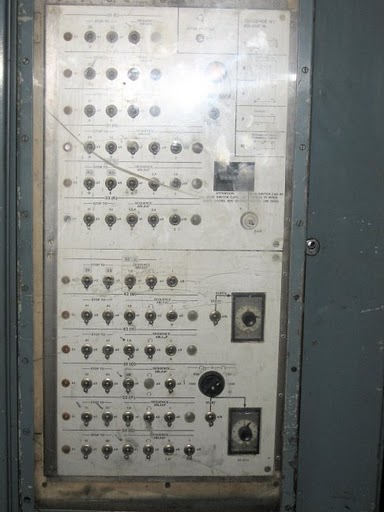
You set the spindle actions (and timers) by using a bank of toggle switches that were located in a panel at the side of the machine. You had switches to enable or disable the spindles (if they weren’t being used) and switches to switch between boring, threading or facing and direction of rotation.
Before each set, that was the second thing you did (the first was cleaning the machine).
Mistakes were made. I’ve made a few (including getting my thumb stuck underneath a spindle flange when it returned too soon (OUCH!)) and some made by others. Usually though these were made when setting the machine and not in production! I’ve seen fast approaches set incorrectly, resulting in the tools slamming into the component, I’ve seen the ends of tool clusters sheared off and taps that got stuck in components on the way round.
Location, location, location
I’ve mentioned that the turret had to be in exactly the same place every time it did its 72 degree rotation. But the units themselves had to all be in the same place too, relative to the turret centreline.
Imagine the very centre of one turret face (it’s a rectangle). Imagine the centre of that rectangle by drawing lines diagonally across the turret face from corner to corner. The exact centre of the turret face must line up with all of the units.
So if you drew a vertical line from the exact centre of the turret face, the top and bottom units (e.g. 21 and 23) would have to have their centrelines in line with that vertical line. Both left and right, and back and forward (so the spindle centreline must be exactly in line with the line drawn vertically from the turret face). Not only that, both units must be in line with the turret centreline and the other unit.
The horizontal unit’s (22) spindle centreline would also need to line up exactly with the centre of the turret face and be exactly perpendicular. Incidentally, the horizontal units (22, 32, 42 and 52) could also tilt and lift, adding complication to an already complicated scenario!
Each spindle had a certain amount of “wiggle room” in them, where you could loosen the holding bolts, then use Allen keys to gently nudge the spindles into position. It was only a small amount of wiggle room, but they weren’t that far out. Usually.
We had a hardened steel cylinder made that would locate on the face of the turret, which would enable us to use as a datum point to align the spindles if necessary. That made it quite “easy” to do, with multiple dial indicators and a copper mallet. Fortunately, this was not a procedure that had to be done very often at all. We only needed to do it if a spindle was removed (and then replaced) for maintenance, or we’d noticed that a measurement had drifted. They were very rare scenarios, fortunately. If you did have to do any realignment, you made damn sure that you tightened those bolts afterwards! (Then rechecked it!)
The tooling
Unfortunately, I can’t find any pictures of the type of tooling we used to use. In fact, I’m beginning to think it may have been unique to us! Nowadays, on the new CNC rotary transfer machines, they use one tool per machining station: that performs one function, like drilling or tapping, or boring.
We often used tooling that would do multiple things in one operation. For example, if we wanted to turn an outside diameter on a casting and put a chamfer on the inside and outside of it, we had a toolset that had two turning tools, diametrically opposed and set to the same height, and cutting diameter as the one required. Also in that tool cluster would be two chamfering tools, one set to chamfer inside and one outside (as it was a chamfer, two matching tools weren’t required as it was considered a light cut). On the station prior to the one with finishing cut, there would be a set of roughing tools, to pre-cut through the casting skin first, to give the final cut a better finish by providing a uniform amount to cut off. All this had to be set using a granite surface table, height gauges, micrometres and dial indicators on stands. And it had to be the right finished size, otherwise you’d have to go back and adjust.
Sometimes it would take days to set these tool clusters up, so once they were finished with on the machine, they were carefully cleaned and returned to storage. Very carefully!
Sometimes the set was easy. We used to make elbows out of a solid brass stamping. It required boring, drilling and tapping on three stations only. That was the quickest runner at 360 per hour and a solid operator favourite on the older machine that rotated quickly.
The coolant
The two AM II machines were the only machines in the factory that used oil for coolant.
Coolant served three main purposes:
- To cool (as the name suggests): both the tools and the components as they were being machined. Too hot and the tool tips that were brazed on, would braze off!
- To lubricate: cutting tools require a bit of lubricant just to keep things from wearing too quickly and to produce some nice smooth surfaces.
- To wash away the debris: cutting brass (or DZR – an type of brass) whether it was bar stock or casting produces small chips, called swarf.
In order to successfully cut brass, the tool cutting rake angle needs to be a negative number (-1 to -3 degrees) in order to prevent the tool from digging in. As a result of that, brass swarf is small, very needle-like and there’s usually a lot of it.
The reason the machines used oil as the coolant, was the inside of the machine. The units that did the machining – had electrical components on them. The motors and the limit switch boxes were all inside the guards of the machine, so the usual water-based coolant would very quickly cause a few electrical issues.
Remembering that these machines are high volume (and surrounded by big metal walls), there was an extraordinarily copious amount of coolant flowing in that space – mostly to wash away the swarf into the swarf collector conveyor at the bottom, but mainly to keep the machine tools cool(ish). After three shifts of continuous running at quite a pace, things did get rather warm!
The brass swarf landed everywhere and anywhere, so after a production run had finished, it was the next setter’s job to clean the machine out. I didn’t mind doing it, to be fair it was quite a relaxing thing to do: attach a rubber hose to a coolant pipe and then have fun hosing down the insides of the machine. After dressing in a full waterproof body suit and wellingtons, of course.
Safety
I’ve mentioned briefly the sliding doors that were on each of the AM II machines. Here’s more detail:
The older of the two machines had a sliding door (they both slid from top to bottom, not side to side, by the way), a foot pedal and two big push buttons, one either side of the sliding door portal. Once the machine had rotated, the operator opened the door by sliding it up and removed the finished component. The chuck would automatically open when the turret reached the front station and an action had to be performed before the turret would rotate again. That action would be the operator removing the finished component, then inserting a new component to be machined, and pressing the pedal by his foot, to close the jaws. Then the operator had to slide the door closed and press both of the buttons that were at either side of the door, at the same time. Only then, when the door was shut and the buttons had been pressed would the cycle continue. If the door was opened before the turret had rotated, then the turret would not rotate until the door was closed and the buttons were pressed. If the buttons were pressed before the door was shut, nothing happened!
The combination of the door interlock and the buttons was to ensure that the operator had their hands well out of the way before a turret rotation occurred.
On the newer machine, the function was similar, but there were no buttons. The act of closing the door triggered the signal to the machine that it was good to continue without pressing any buttons. The foot pedal function remained the same – if the jaws weren’t closed the machine wouldn’t cycle.
The doors were the only bits on the machine that had safety interlocks. You could (in theory) remove any other of the big steel panels to gain access to the inside of the machine without it stopping. It would be a very foolish thing to do however, as you’d get showered in coolant oil and hot swarf. The advantage of that was that if you were in the back setting the units up, you didn’t have to shut yourself in. As you wouldn’t run all the units at the same time (or any coolant), it was safe enough.
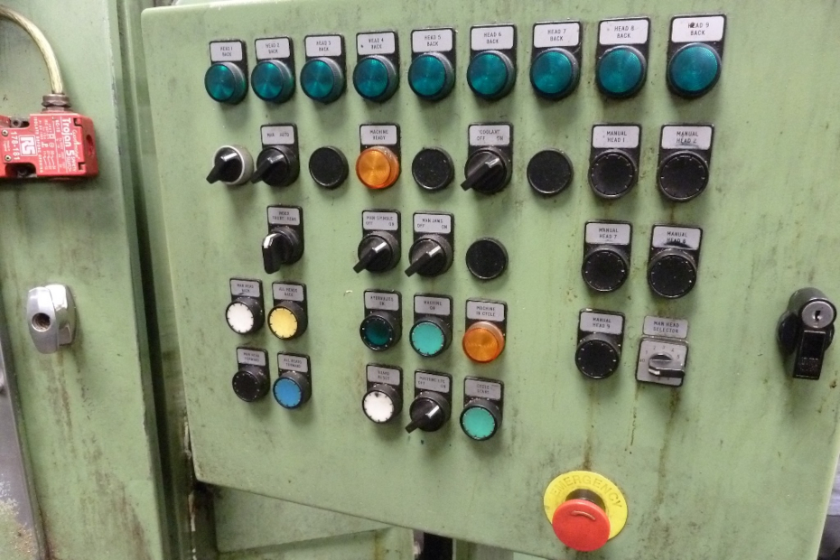
Controlling and driving the beast
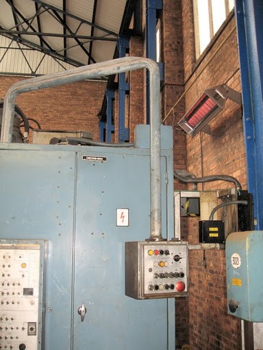
Aside from the switch panel on the side, there was a “remote” control panel. I say remote, but it was suspended from a big swivel arm that originated from somewhere at the top of the machine. It could swing round from the operator station at the front, to right around the back of the machine.
From that panel, you could select automatic or manual mode, control the coolant on/off and the obligatory emergency stop. You also had a rotary toggle to select individual units, which you could then run and send in and out. These controls were only used in manual, when the machine was being set.
The panel had to be well within operator reach when the machine was running. There were Emergency Stop buttons placed in strategic locations by the front loading door etc. but we always felt a bit better if you could slam the one on the panel (for show, more than anything else!).
Finishing touches
Automatic mode was always my favourite bit. Once you’d set your units up individually to do the required machining operations, the only thing left to do would be to try it on full automatic. When doing the initial setting (to get the units right), you would only ever install one set of jaws. That way, when you went into full automatic mode, your tooling was guaranteed not to hit any empty jaws – as they weren’t there. You double or even triple checked that no units that weren’t supposed to be running were turned off and then you flipped the switch from manual to auto and pressed the start button. All of the active units would all start and operate at the same time. Noisy, impressive and it would make the lights in the factory dim very, very briefly.
When you were happy with auto mode, you’d put any guards back on (that you’d taken off), arrange the coolant feed pipes into a suitable position to be able to wash away swarf and cool/lubricate, and then you would cut a new component, for real, in full auto with coolant.
Then you’d bugger off somewhere quiet and measure it!
More often than not, you would have to make some tweaks to get final measurements within the drawing tolerances. Cutting without coolant could produce slightly different results than cutting with, so you’d have to do at least one component with coolant on. Once you were happy with that, then you set the four other sets of jaws on the turret (noting where they were supposed to be), you did yet another full auto test with coolant, this time cutting on components on all four sets of jaws and then you sat and measured all of them.
Any final tweaks? No? Put it up for a first-off.
Quality control
I’ve mentioned elsewhere that I’d worked in the Quality Control department for quite a long time. So I could measure and I knew how to use the mensuration tools that the shop inspectors did. That was all very well, but I was expected to get everything right all of the time!!
The job of the inspector is of course to make sure that the components you’re churning out at 250 per hour are all the right size and will work. To that end, each stage of machining, whether it was my machine or another stage, had it’s own set of quality control guidelines. These guidelines were a set of measurements set out on a form and a drawing to accompany it.
Before any production started however, the components had to have what was known as a “first-off”. Called so, as a setter would set a machine, machine a component and submit that component – the first one from the batch – to the inspector for checking, to make sure it was correct before production started. The setter provided the component, the drawing and any gauges that were required to check the components.
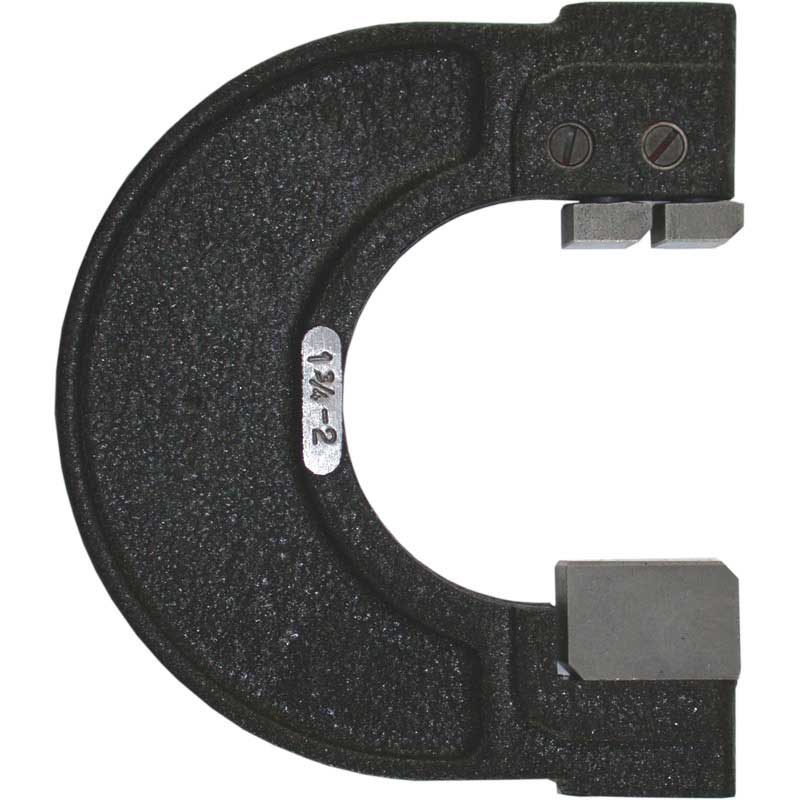
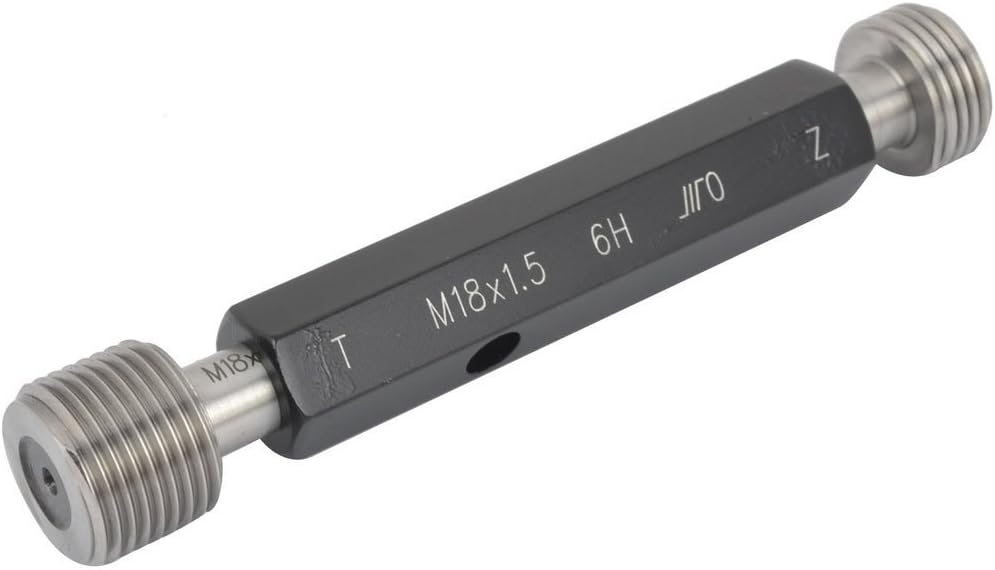
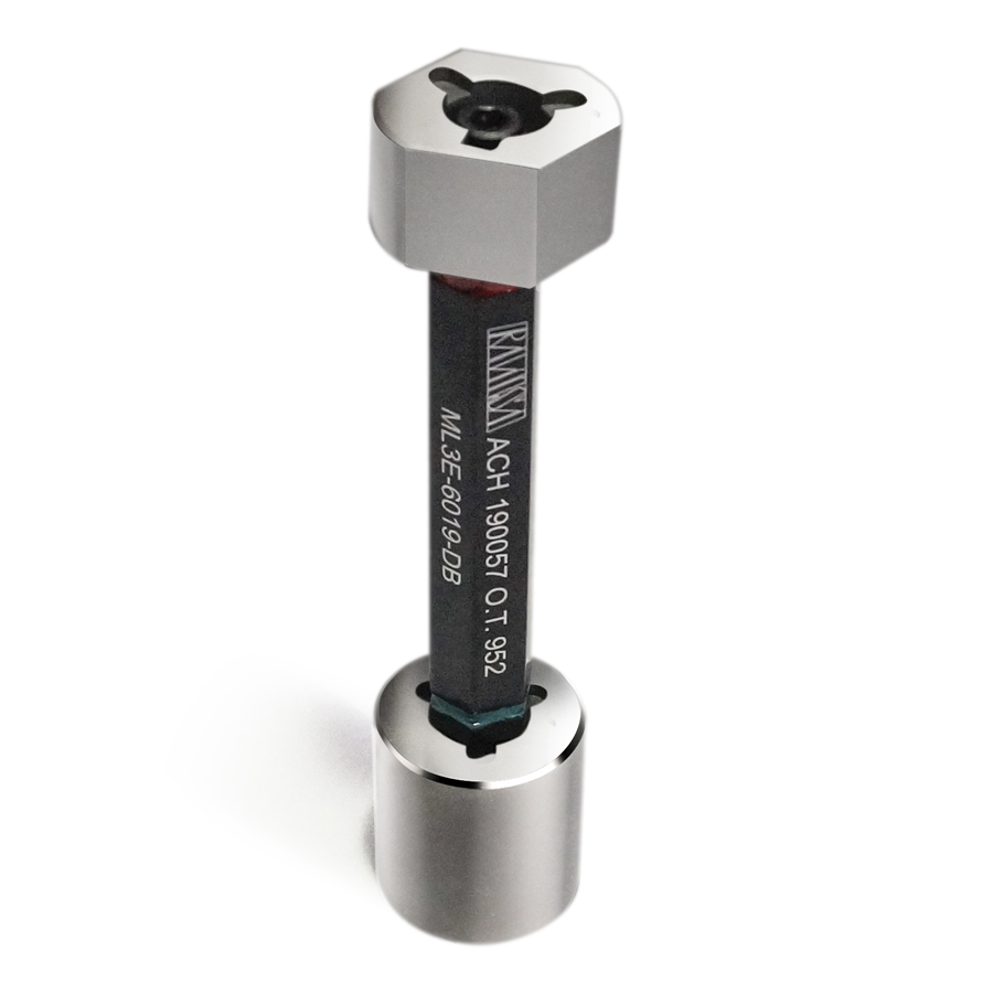
Gauges were a quick and easy way to check that a diameter – of a hole or a thread or the machined outside of a component – was machined within the tolerances specified on the drawing, This was meant for the operator and the inspector to quickly and easily check whether a hole for example, had become to big or small to fit the gauge, resulting in incorrect components. Incorrect components could result in either rework, or scrap. Neither of which was good for your reputation as a setter, or for the company. Gauges had two areas – a go and a no-go. The go end would fit into, or over the component, the no-go wouldn’t. If either of those became anything otherwise, something was wrong.
In the case of the AM II, there were five stations that executed machining at some point in a full rotation of that turret. Therefore for your first-off, you submitted five components, one from each set of jaws.
The inspector retrieved the relevant quality control form applicable to the component’s machining stage. The inspector worked through the form, measuring the required bits and pieces and carefully measuring all the critical areas to ensure it was all within drawing tolerances and was fit for purpose. Sometimes tweaks had to be made, sometimes not. In my case it really did have to be perfect, otherwise both the inspectors and the other setters would have taken the piss relentlessly!
Once approved, the QC form was duly completed, the first-off(s) were stored for reference and production was allowed to begin.
The QC form stayed at the side of the machine, where an inspector would regularly take samples, measure and log it down for posterity.
Production
These machines were big, smelly, noisy and the operators hated them. They could also be a bit problematic until the point at which they warmed up. No, honestly! Especially in the first hour or so and double especially for the complex components. As you’d done your first off, the first few hundred components would be fine.
Then, as the machine warmed up, things started expanding and measurements could creep out of tolerance. I would ask the operator to keep a close eye on the components for the first couple of hours, using their eyes and the gauges. If anything seemed off, or a gauge was getting tight, let me know. Little tweaks usually had to be done early on, but once the machine warmed up, it was as consistent as the rising and setting of the sun.
The operator
Never mind the machine or the components, the operator was the element that made or broke your production run. Quite literally in some cases. Good operators were the ones that kept a close eye on things, never failed to load the jaws correctly and checked the components frequently with the required gauges and – crucially – knew what the gauges were for!
The bad ones were the ones that didn’t want to be there and really let you know about it! Constant whingeing and whining until they misloaded something then BANG! That meant they were off to do something else, and I had a toolset or two to repair. Not happy days.
Incidentally, if you did have a tool or toolset break, you had to fix it and resubmit it for inspection to make sure it was still OK.
Other Diedesheims are available
The AM II machines weren’t the only Diedesheim products we had in the factory.
The LSA
[Click the image on the left for a larger version]
We had something called an “LSA”. An LSA was a much smaller version of an AM II. It had a turret – but mounted vertically but still five sided. The chuck and jaw system was the same as the AM II, as were the tooling and spindles. Except this time, the spindles were mounted with the motors and gearboxes outside of the machine, with just the tooling end inside. This meant that we could use water-based coolant in them. (That pleased the operators!)
The LSA was also a high volume machine, but on a much smaller scale. The advantage of the spindle gubbins being on the outside was that you could make adjustments in production if you wanted to, without stopping the machine and climbing inside. Other than that, everything else was the same as the AM II. The tooling was the same principle, the units were named the same (21, 22, 23 etc.) the unit and turret alignments were the same principle and the turret still located in pins and castellations, but horizontal ones this time.
It was a much smaller machine however, and as such was a bit more sensitive to thumps and bangs. A clumsy forklift operator dropping a full box of castings for example could throw some measurements off, at least temporarily.
There were no doors with safety interlocks on this one, it was steel cover with rubber flaps on it that would present the turret jaws as the turret made a rotation. All the operator had to do was take the finished component out, load a new one, clamp the jaws with the foot pedal and press two big green buttons – one on each side.
The Didomats
Now I can’t find any evidence of these machines at all on the internet, so I’m wondering if they were actually called Didomats. I can find Diamats, but not Didomats. Anyway.
These were round(ish) horizontal turret machines, but these had eight turret stations instead of five with turret shaped like a very shallow cone. The units were outside again, so we could use water-based coolant. The units were the same type as the LSA used, with adjustment on the outside, so we could make adjustments without turning the machine off.
The big difference between the Didomats and the LSA (and AM II for that matter) was the fact that you could index the turret by two positions, instead of just one for the other machines. That meant a full rotation was only fours stops round, (instead of five for the others) and you would get two finished components per stop.
The operator loaded two components – one in each turret station and pressed the foot pedal. There were no doors on the Didomats, just guard plates. Once the operator had clamped the jaws shut with the components in them, they pressed two big green buttons – one on each side.
These machines turned out to be quite popular, as when the Time & Motion people had timed how long it took to machine a single component, they had timed it on a different machine! So when we started producing two at a time, the operator could make their piecework quite easily. I enjoyed a few bought coffees because of that.
Wolverhampton Didomats
The company I worked for merged with another shower/bathroom fitting company that was based in Wolverhampton. The Wolverhampton factory had its own foundry (as the company I worked for did) and their own machine shop. At the time the merger happened, I was sent up to look at their quality control procedures and their foundry procedures.
A few of us drove up there, had a guided tour around the factory – which included a silent row of Didomats (three of them, as I recall). I asked if they were in use, and was told that no-one knew how to set them, as the chap that used to do it retired and he never wrote anything down, or taught anyone how to do it before he left!
It turned out they used them for only roughing out work, as they didn’t hold any sort of accuracy (unlike ours) for fine machining. We (I) offered to teach them how to set them and set them up so that they could produce reliable results, however our (my) offer was refused, as they had found alternative methods of machining the components and the Didomats were to be sold for scrap.
That was a crying shame.
I nearly didn’t change careers!
When I made the decision to change careers from production to computing, it really was with a heavy heart that I left those machines behind. I loved setting those machines, despite how noisy, smelly and bloody-minded they could be.
I considered long and hard about leaving, wondering how long they had left as their working life. But the writing was on the wall for them. CNC machining was taking over a great deal at the time and the company was investing a lot of money into that. Nobody wanted to maintain, work on or spend any money on the old AM II’s and so I left before horrible things happened to them.
Like the Wolverhampton Didomats, I thought it a shame. OK, it was a dirty smelly sometimes cantankerous old beast, but it still was a highly accurate high volume production machine.
I wish I’d bought one of them for my garden shed now. Oh well.
Appendices
There now follows some sets of appendices, A, B and C.
- Appendix A is a list of the specifications of the AM II. The specs didn’t change much between the older and newer one!
- Appendix B is an example of the components we used to machine. With pictures.
- Appendix C is a very brief history of the manufacturer of the AMII: Maschinenfabrik Diedesheim, with some links to further information.
Appendix A
AMII Specifications:
12 spindle, 5 station, 3 axis rotary transfer machine with horizontal indexing turret.
Equipped with 5 x 2-jaw-chucks (300 mm dia.)
Spindle diameter 65 mm
Electrics 400 Volt/3 phase/50 Hz
Station 1:
Load / Unload
Station 2:
Unit 2.1 Drilling/Boring spindle
Unit 2.2 Drilling/Boring spindle
Unit 2.3 Drilling/Boring spindle
Station 3:
Unit 3.1 Drilling/Facing spindle
Unit 3.2 Combination Drilling & Threading
Unit 3.3 Drilling/Facing spindle
Station 4:
Unit 4.1 Combination Drilling & Threading
Unit 4.2 Drilling/Facing spindle
Unit 4.3 Combination Drilling & Threading
Station 5:
Unit 5.1 Combination Drilling & Threading
Unit 5.2 Combination Drilling & Threading
Unit 5.3 Combination Drilling & Threading
Machining units type “HYP 65” AND “GP 65”
Drilling units stroke 100/150 MM.
Threading units stroke 80 MM.
Stroke restrictors fitted on units 22, 32, 41 and 42.
Horizontal units can be swivelled (adjusted) and off-set from centreline.
Bottom units can be swivelled (adjusted) and off-set from centreline.
Weight of machine: 15000 kgs approx.
Space requirement: 3160 MM x 2235 MM x 2750 MM HIGH.
Spindle speeds:
Units: 2.1, 3.1, 3.2, 4.1, 4.2, 5.3: 56 – 90 – 140 – 224 – 280 – 355 – 450 – 560 – 710 – 1120 – 1800 – 2800 RPM
Units: 2.2, 2.3, 3.3, 4.3, 5.2: 280 – 450 – 710 – 1120 – 1800 – 2800 RPM
Unit: 5.1: 28 – 45 – 56 – 71 – 90 – 112 – 140 – 180 – 224 – 280 – 355 – 450 – 560 710 – 900 – 1120 – 1400 – 1800 – 2800 RPM
Appendix B
This is an example of the sort of thing we used to machine on the AMII, the type of tools we used and how we used to do it.
This is the shower body. It’s no longer sold by the company, however we were obliged to provide spares for 10 years minimum, so we had the occasional production run of them.
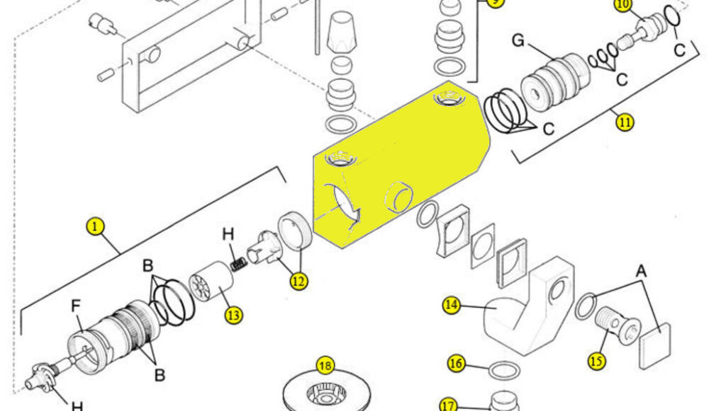
The yellow block is the body itself. It came to us with four milled sides (in the picture, the top, bottom and left and right sides) so we had a decent surface that our jaws could clamp on to.
Our job was to bore the left and right bores (in the picture), so that the flow and temp cartridge would screw in. In the above picture, that’s No. 1 and No. 11.
We also had to drill and tap the hole at the front, so that the threaded spigot (No. 15) could attach the elbow (No. 14). We had to bore the hole, undercut it, ensure there was a through hole into the inside of the casting, undercut it to clear the thread and finally thread it!.
[Click the image below for a larger version]
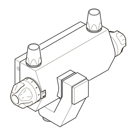
This is the complete shower assembled, showing the temp knob on the left, the flow knob (on/off) on the right and the elbow at the front to which you attached your shower hose and head.
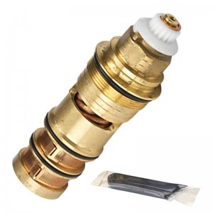
The cartridges that fitted in the shower body looked like this. See those black rings? They are rubber “O” rings. Those O rings had to land just in the right place when the cartridge was screwed in, so that they would seal against a smoothly bored surface.
The inside of the shower body was divided into chambers, separated by those O rings, to direct hot and cold water and mix it to exit the shower.
The picture is of the thermostatic cartridge (that controlled the water temperature). On the other side was a similar cartridge that controlled the flow of water. The O rings and sealing faces were equally as important on that side too!
We had several operations to do:
- The component was clamped along its longest sides so that it sat vertically in the jaws, with the cast spigot for the hole facing towards the front.
- The first units round (the 20’s) would rough out the top and bottom set of bores and would drill a hole through the front spigot into the space behind.
- The second units would finish the top and bottom bores, chamfer the edges of the internal chambers (in order not to break the O rings when they were fitted) and the front spigot hole would be bored to accept the thread.
- The third unit was just the horizonal unit (42) with a facing head fitted. This would go in and undercut the bottom of the thread hole, to clear the thread.
- The last units (the 50’s) would thread top and bottom for the cartridge (you can just see the thread under the very top O ring) and thread the spigot hole.
Next time round, the operator removed the finished component, did a visual check and put it into a pallet box. Every ten components, the operator would checks the bore sizes and the threads with gauges.
The tooling for cutting the bores (and the thread bore) was for the setter, reasonably simple.
[Click the image on the right for a larger version]
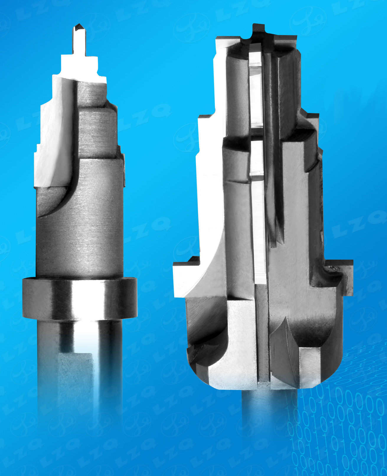
Boring tools were made by the in-house toolroom and would be bespoke for each component type. They looked very similar to the picture, being made up of carbide tips brazed to a steel shank.
The required diameters and clearances were ground on by specialist grinders in the tool room and they made five or six of them at a time – especially for the AMII! If a tool shattered for some reason, you wanted a replacement pretty quick!
At the time I was setting the machines, the machine tooling, the boring tools, the undercut tools were all made from brazed carbide tips. This was because the tooling was actually made before the introduction of replaceable carbide tips. They were in use on the CNC machines, of course.
[Click the image on the left for a larger version]
The roughing bore tools were designed to remove any excess material from inside the casting. If there were any bits of flash, or lumps on the sides, the roughing tool was used to remove it, ahead of the finishing tool, which would make a much finer cut.
However, we were dealing with castings. Casting can suffer from broken cores, which will produce either a big lump of brass in the middle of the casting, or a blocked inner hole completely. If that was the case, the roughing boring tool would hit it and either break, or dislodge the component.
This was where the “aware” operator was a godsend. We asked them to look at the castings before they went in and give them a quick once-over when they came out. As a reward – rather naughtily – we’d speed things up a little for them and give them some extra components that we’d machined. All helped towards the piecework bonus! (Shhh, don’t tell anyone!)
Appendix C
The AMII, the LSA, the Didomats were all made by the same machine tool company: Maschinenfabrik Diedesheim, based in the Mosbach district of Diedesheim, Germany.
The history of the company isn’t that complicated, however it took quite a bit to discover where it came from, due to company buy-outs, name changes etc.
Maschinenfabrik Diedesheim started in 1947, as one of the predecessor companies of the current incarnation: Hüller Hille. Diedesheim made several varieties of machine tool, including the AMII and Didomats etc. right up until 1984, when the company was acquired by Thyssen Maschinenbau.
Whilst rotary transfer machines were – and still are being manufactured, they were all now all that modern CNC and bear little resemblance to the beauty of the old electro hydraulic beasts.
The current company: Hüller Hille has had several takeovers and acquisitions, several ups and downs, but still remain in the business of making machine tools to this day. They are still based where the original factory was in Diedesheim, Germany.
For more Maschinenfabrik Diedesheim history, have a look at the Wikipedia page, (it’s in German, but most browsers will translate) for the current manufacturer of rotary transfer machines, have a look at Hüller Hille. That site has an English language version.